As Found
Read Modify Write Register Exercise
Task
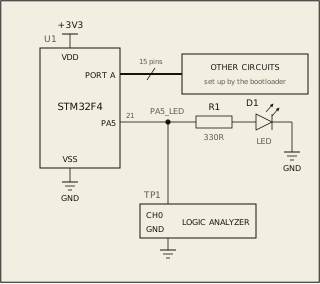
On most boards a small program called a bootloader runs before your code. It has already set up some of port A's pins for other circuits on the board.
Blink the LED on PA5 three times, then leave it off: high, low, high, low, high, low The registers are on the Datasheet tab, under GPIOA.
Circuit
Pass condition
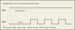
PA5 goes high, then low, three times, and ends low. Nothing else on port A may change. Timing is not graded.
Notes
The bootloader runs before main, and each test is a board it set up differently.