Wait for It
STM32 Data Ready Pin Exercise
Task
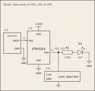
A sensor takes its time to finish a measurement and cannot say in advance when it will be done. When a new reading is ready, the sensor raises a wire called the data-ready line, and the chip watches that wire. On this board the line comes in on PA0, and the LED on PA5 shows that the chip has seen it.
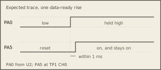
Make the LED follow the line, like this: PA0 low: LED off. PA0 rises: LED on within 1 ms, and on for good. PA0 rises at most once, at a moment you cannot predict. The registers are on the Datasheet tab, under GPIOA.
Circuit
Pass condition
PA5 rises once, within 1 ms of PA0, and stays high. If PA0 never rises, PA5 never moves.
Notes
PA0 is already an input when the program starts, so it needs no setup.