Scroll
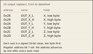
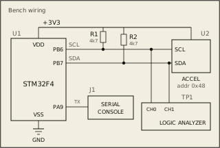
A 3-axis accelerometer (LIS3DH-style) is connected to I2C1 at slave address 0x48. The raw acceleration data lives in six consecutive registers starting at 0x28:
0x28 OUT_X_L (X axis, low byte) 0x29 OUT_X_H (X axis, high byte) 0x2A OUT_Y_L (Y axis, low byte) 0x2B OUT_Y_H (Y axis, high byte) 0x2C OUT_Z_L (Z axis, low byte) 0x2D OUT_Z_H (Z axis, high byte)
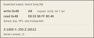
The sensor supports auto-increment addressing: setting bit 7 of the register address (e.g., 0x28 | 0x80 = 0xA8) tells the sensor to advance its internal pointer after each byte, so all six bytes can be read in a single I2C transaction.
Read all 6 bytes in one multi-byte read, combine each low/high pair into a signed 16-bit value, and print the result via UART:
X:<value> Y:<value> Z:<value>
For example, if OUT_X is 256, OUT_Y is -100, and OUT_Z is 16200:
X:256 Y:-100 Z:16200
The starter code provides I2C initialization, UART helpers, and register definitions. Your job is to implement the multi-byte read and format the output.