Switchboard
STM32 GPIO Input Register Exercise
Task
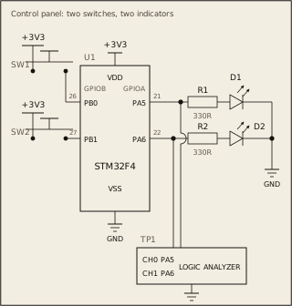
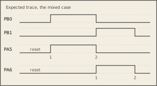
The switches on PB0 and PB1 go on and off while your program runs. Make each LED follow its switch for as long as the board runs: if PB0 is on -> PA5 on; if PB0 is off -> PA5 off. if PB1 is on -> PA6 on; if PB1 is off -> PA6 off. The registers and bit fields are on the Datasheet tab.
Circuit
Pass condition
Each LED changes only when its own switch does. A glitch while you set up the ports counts as an edge too.
Notes
The bench drives PB0 and PB1 directly, so you need no pull-up or pull-down. This question needs no clock enable.