Light Switch
STM32 Read Button State Exercise
Task
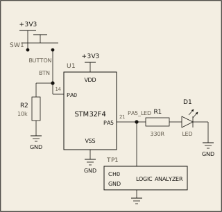
While your program runs, the button on PA0 is pressed and released. Read it and control the LED on PA5: if the button is pressed -> LED on; if not pressed -> LED off. Repeat this for as long as the board runs. The registers and bit fields are on the Datasheet tab.
Circuit
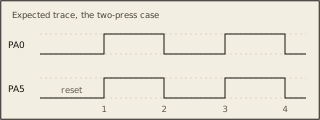
Pass condition
PA5 must match PA0 at all times, with no extra edges.
Notes
This question needs no clock enable.