Intake
STM32 UART DMA Receive Debug
Symptom
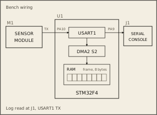
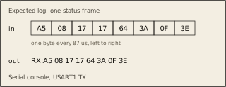
The sensor module sends A5 08 17 17 64 3A 0F 3E. The board logs RX:3E 00 00 00 00 00 00 00. The registers and bit fields are on the Datasheet tab.
Circuit
Pass condition
The frame lands in RAM in one eight-byte DMA2 Stream 2 transfer. The log prints RX: and the bytes in hex, in the order they arrived.
Notes
The bench sends the frame once, after reset. USART1 RX is DMA2 Stream 2, channel 4. On this bench only DMA2 needs its clock enabled, and the program enables it.