Automaton

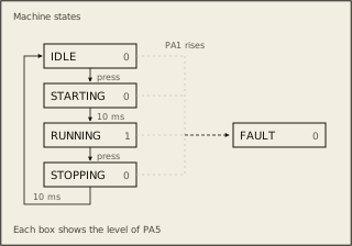
A colleague left scaffolding for a table-driven motor controller state machine, but never finished the implementation. The machine has five states: IDLE, STARTING, RUNNING, STOPPING, and FAULT. A button on PA0 triggers operational transitions, and a fault line on PA1 forces the machine into FAULT from any state.

The transition table and state enum are already defined. You need to implement the engine: process GPIO inputs, look up transitions in the table, enforce minimum dwell times, drive output pins, and log each transition over UART.

State machine behavior:

  • IDLE: motor off, status LED off. Button press -> STARTING
  • STARTING: status LED on. After 10ms dwell -> RUNNING
  • RUNNING: motor on (PA5 high), status LED on. Button press -> STOPPING
  • STOPPING: motor off, status LED on. After 10ms dwell -> IDLE
  • FAULT: motor off, status LED on. Terminal state (no exit)
  • Any state + PA1 high -> FAULT immediately
  • Button presses that arrive during a timed dwell (STARTING or

STOPPING) are discarded, not queued

GPIO assignments:

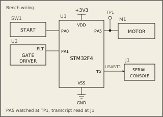
  • PA0 = button input (active-high, active on rising edge)
  • PA1 = fault input (active-high)
  • PA5 = motor enable output (high = motor on)
  • PA6 = status LED output (high = active)

Every state entry is logged over UART as one STATE:<name> line, where <name> is the state's name exactly as listed above (IDLE, STARTING, and so on). The machine logs its initial IDLE state at boot, then one line each time it enters a new state.

The starter code provides the transition table, state enum, ISR handlers (EXTI0 for button, EXTI1 for fault, SysTick for dwell), and UART helpers. You need to implement: GPIO/EXTI init, timer configuration, output pin control, dwell wait logic, and the main loop transition engine.

TIM2 should be configured with PSC=15 and ARR=9999 (CEN enabled). SysTick should fire every 10ms for dwell timing. Use WFI to sleep between events.

Loading the interactive arena.