Conductor

A motor control board needs two coordinated timing channels. TIM2 runs a fast control loop at 1kHz, while TIM3 drives a slower telemetry sample at 250Hz, giving a precise 4:1 ratio between the channels.

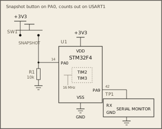
Your job: bring up both timers from scratch with interrupt-driven overflow counters. The STM32F4 runs at 16MHz. After the counters have been running, print a summary via UART.

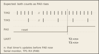
Expected UART output format: T2:<count>\n T3:<count>\n RATIO:4\n

where <count> is the number of overflow interrupts each timer has fired. The grader matches the summary exactly: it expects a TIM2 count of 75 and a TIM3 count of 18, with RATIO computed by integer division (75/18 gives 4). Snapshot both counters and print once the TIM2 count reaches

  1. The register checks also expect both prescalers to divide the 16MHz

clock to a 1MHz tick, with auto-reload values of 999 on TIM2 and 3999 on TIM3.

The starter code provides register maps for both timers, UART helpers, and an NVIC enable helper. You need to enable clocks, configure prescalers and auto-reload values, enable interrupts, write both ISR handlers, and print the results.

Loading the interactive arena.