Flight Recorder
SPI Control Register Exercise
Task
Once after reset, set RUN, bit 3 of U2's CTRL register (0x2D), and leave CTRL's other bits as they are. Print CTRL as U2 reads it back. The registers and bit fields are on the Datasheet tab.
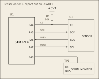
Circuit
Pass condition
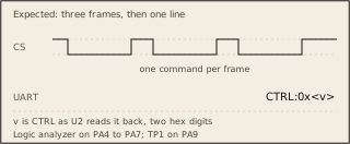
The logic analyzer must show only the commands the task needs, each in its own CS frame. The terminal must print CTRL:0x and the byte CTRL then has, in two hex digits.
Notes
U2 is the bench's sensor. A frame starts with the register byte, bit 7 set to read. Send 0x00 where a byte has no data. Your program is built and run at -O0, then at -O2. Both must pass.