Calling Card
STM32 CAN Transmit Frame Exercise
Task
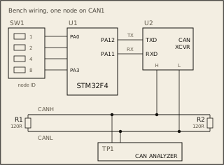
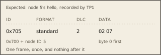
At power-up, send one hello frame on CAN1: standard ID 0x700 plus the node ID, two data bytes, 02 then 07. Send it once. The registers and bit fields are on the Datasheet tab.
Circuit
Pass condition
The analyzer on the bus records exactly one frame, as figure 2 shows for node 5. Your program confirms each mode change it asks for in MSR and ends in normal mode.
Notes
node_id() is given. It returns switch SW1's setting, 1 to 15. The bench sets SW1 before power-up. Bus at 500 kbit/s: CAN1_BTR = 0x00050003. No clock enable is needed.