Stopwatch
STM32 Timer Pulse Measurement Exercise
Task
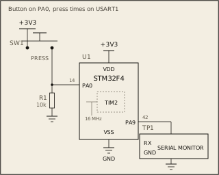
The bench presses and releases SW1 on PA0 while your program runs. For as long as the board runs, time every press with TIM2 ticking once a microsecond (PSC = 15). The registers and bit fields are on the Datasheet tab.
Circuit
Pass condition
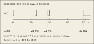
If SW1 is released -> print how long it was held in whole ms, rounded down: "23 ms". Until then -> print nothing. TIM2 must tick once a microsecond from reset.
Notes
TIM2 is clocked at 16 MHz. The given code sets up USART1 and printing. Your program is built and run at -O0, then at -O2. Both must pass.